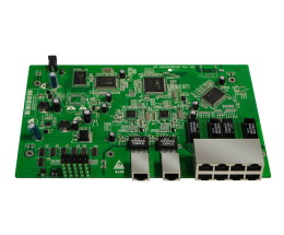
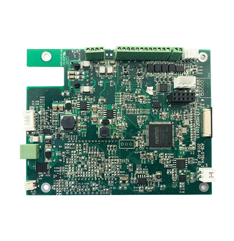
Rigid PCB Assembly: A Comprehensive Guide
If you are involved in the production of electronic devices, you may have heard of rigid PCB assembly. Rigid PCBs, or printed circuit boards, are the backbone of electronic devices, providing mechanical support and electrical connections for the components. Rigid PCBs can be found in everything from smartphones to medical equipment to automobiles.

Rigid PCB assembly involves the process of attaching electronic components to a rigid PCB. The components are soldered onto the board, creating a permanent electrical connection. This process can be done by hand or by machine, depending on the volume of production. The assembly process is a critical step in the production of electronic devices, as it ensures that the components are securely attached to the PCB and that the device will function as intended.
Overview of Rigid PCB Assembly

Rigid PCBs, or Printed Circuit Boards, are used in a wide range of electronic devices and equipment. They are made of a rigid substrate material, and are designed to provide a stable and reliable platform for electronic components. Rigid PCB assembly is a complex process that requires careful attention to detail and a high degree of expertise. In this section, we will provide an overview of the components of rigid PCBs and the different types of rigid PCBs available.
Components of Rigid PCBs
Rigid PCBs are composed of several key components, including the substrate material, copper traces, and electronic components. The substrate material is typically made of fiberglass or a similar material, and provides a rigid base for the PCB. Copper traces are used to connect the various electronic components on the board, and are etched onto the substrate material using a chemical process. Electronic components, such as resistors, capacitors, and transistors, are then mounted onto the board using a variety of techniques.
Types of Rigid PCBs
There are several different types of rigid PCBs available, each with its own unique characteristics and applications. Single-layer PCBs are the simplest type of rigid PCB, and are used in a wide range of electronic devices. Double-layer PCBs are more complex, and are used in applications where space is at a premium. Multilayer PCBs are the most complex type of rigid PCB, and are used in high-end electronic devices and equipment.
In addition to these basic types, there are also a number of specialized rigid PCBs available. High-frequency PCBs, for example, are designed to operate at high frequencies and are used in applications such as wireless communication systems. High-temperature PCBs are designed to operate at high temperatures, and are used in applications such as aerospace and defense systems.
Overall, rigid PCB assembly is a complex process that requires a high degree of expertise and attention to detail. By understanding the components of rigid PCBs and the different types available, you can make an informed decision when selecting a PCB for your specific application.
PCB Assembly Process

PCB assembly is a crucial step in the manufacturing process of electronic devices. It involves the transformation of raw PCBs into populated boards that can perform designated functions. Proper assembly is essential to ensure that the PCB becomes the brain or backbone of an electronic device. This guide will walk you through the PCB assembly process.
Soldering Techniques
Soldering is a process that involves joining two metal surfaces using a filler metal. It is a critical step in the PCB assembly process, as it ensures that electronic components are securely attached to the PCB. There are two primary soldering techniques used in PCB assembly: surface mount technology (SMT) and through-hole technology (THT).
Surface Mount Technology
Surface mount technology is a soldering technique that involves attaching electronic components to the surface of a PCB. It is a widely used technique in PCB assembly due to its high level of accuracy and efficiency. SMT components are much smaller than THT components, which allows for a higher density of components on the PCB. SMT components are also more resistant to vibration and shock.
Through-Hole Technology
Through-hole technology is a soldering technique that involves attaching electronic components to the PCB by inserting them through holes in the board. THT components are larger than SMT components, which makes them easier to handle during the assembly process. THT components are also more durable and can withstand higher temperatures than SMT components.
In summary, PCB assembly is a critical step in the manufacturing process of electronic devices. Soldering is a crucial aspect of PCB assembly, and there are two primary techniques used: surface mount technology and through-hole technology. Each technique has its advantages and disadvantages, and the choice of technique depends on the specific requirements of the project.
Testing and Quality Assurance
When it comes to rigid PCB assembly, testing and quality assurance are critical to ensuring that the final product meets all product specifications and industry standards. There are several methods of testing and quality assurance that are commonly used in PCB assembly, including Automated Optical Inspection and Functional Testing.
Automated Optical Inspection
Automated Optical Inspection (AOI) is a common method of testing for PCB assembly. This method uses cameras and software to inspect the PCB for defects in solder, components, and other aspects of the assembly process. AOI can detect defects that may not be visible to the naked eye and can help to ensure that the final product meets all quality standards.
Functional Testing
Functional testing is another important method of testing for rigid PCB assembly. This method involves testing the PCB to ensure that it functions as intended. This can include testing the PCB for electrical performance, as well as testing the PCB for mechanical performance. Functional testing can help to ensure that the final product meets all product specifications and industry standards.
In addition to these testing methods, there are several other quality assurance measures that are commonly used in rigid PCB assembly. These measures can include visual inspection, quality control testing, and more. By using these methods, manufacturers can ensure that their products meet all quality standards and are ready for use in a variety of applications.
Design Considerations for Rigid PCBs
When it comes to designing a rigid PCB, there are several important considerations that you need to keep in mind to ensure that your design is optimized for manufacturability, assembly, heat dissipation, and electrical performance. In this section, we will discuss two key considerations: layout and routing, and thermal management.
Layout and Routing
The layout and routing of your rigid PCB is critical for ensuring that your board functions as intended. When designing your layout, it’s important to optimize it for manufacturability. This means ensuring that there is adequate clearance between traces and components, and that your board is designed in a way that is easy to manufacture.
Routing is also an important consideration when designing a rigid PCB. You need to ensure that your traces are routed in a way that minimizes crosstalk and interference, and that your board is designed in a way that is easy to assemble.
Thermal Management
Thermal management is another important consideration when designing a rigid PCB. You need to ensure that your board is designed in a way that allows for proper heat dissipation, and that your components are not subjected to excessive temperatures.
One way to achieve proper thermal management is to use a copper layer on your board. Copper has excellent thermal conductivity, which means that it can help to dissipate heat away from your components.
Another way to achieve proper thermal management is to use a heat sink or a fan. These components can help to dissipate heat away from your board and your components, ensuring that your board functions as intended.
When designing a rigid PCB, it’s important to keep in mind the layout and routing of your board, as well as its thermal management. By optimizing your design for these considerations, you can ensure that your board functions as intended and is reliable over the long term.
Challenges and Solutions in Rigid PCB Assembly
Component Placement
One of the challenges in rigid PCB assembly is component placement. When designing a rigid PCB, you need to ensure that components are placed in such a way that they don’t interfere with each other. You also need to ensure that there is enough space between components to allow for proper airflow and cooling.
To overcome this challenge, you can use software tools to simulate the placement of components and optimize the design for space and airflow. You can also use guidelines from the manufacturer to ensure that you are placing components in the optimal locations.
Signal Integrity Issues
Another challenge in rigid PCB assembly is signal integrity. When designing a rigid PCB, you need to ensure that there is minimal signal loss between components. This can be particularly challenging when dealing with high-speed signals.
To overcome this challenge, you can use software tools to simulate the signal path and identify potential areas of signal loss. You can also use guidelines from the manufacturer to ensure that you are routing signals in the optimal way.
In addition, you can use shielding and grounding techniques to minimize signal loss and ensure that signals are not affected by external interference.
Overall, while there are challenges to rigid PCB assembly, there are also solutions available to overcome them. By using software tools, guidelines from the manufacturer, and best practices, you can ensure that your rigid PCB design is optimized for performance, reliability, and manufacturability.


