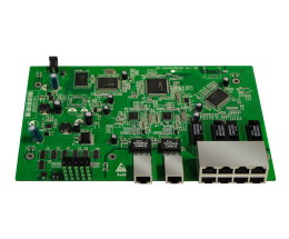
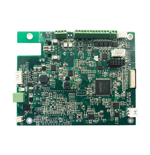
PCB Assembly PDF: A Comprehensive Guide to PCB Assembly Process
PCB assembly is an essential process in the production of electronic devices. It involves assembling electronic components onto a printed circuit board (PCB) to create a functional device. PCB assembly is a complex process that requires a high level of precision and attention to detail. Errors in the assembly process can result in non-functional devices, which can be costly and time-consuming to fix.

To ensure the success of the PCB assembly process, it is essential to have a thorough understanding of the process and the various techniques involved. One way to gain this knowledge is through the use of PCB assembly PDFs. These documents provide a comprehensive overview of the PCB assembly process, including information on the various components involved, the assembly techniques used, and the tools and equipment required. PCB assembly PDFs can be a valuable resource for anyone involved in the production of electronic devices, from engineers and designers to technicians and assemblers.
Overall, PCB assembly is a critical process in the production of electronic devices, and it is essential to have a thorough understanding of the process to ensure success. PCB assembly PDFs can be a valuable resource for anyone involved in the production of electronic devices, providing a comprehensive overview of the process and the various techniques involved.
Basics of PCB Assembly

PCB assembly is an essential step in electronics manufacturing, transforming raw PCBs into populated boards that can perform designated functions. The process involves the assembly of electronic components onto a printed circuit board (PCB) using automated machines or manual labor.
Components of PCB Assembly
The basic components of a PCB assembly include the PCB, electronic components, and solder. The PCB is the foundation of the assembly, and it provides a platform for the electronic components to be mounted on. The electronic components are the active and passive elements that provide the functionality of the circuit. Solder is the material used to join the electronic components to the PCB.
PCB Assembly Process
The PCB assembly process involves several steps, including solder paste application, component placement, soldering, inspection, and testing. The process can be done manually or using automated machines, depending on the complexity of the assembly.
The first step in the process is the application of solder paste to the PCB. This is done using a stencil that is placed over the PCB, and the paste is applied through the openings in the stencil. The next step is component placement, where the electronic components are placed onto the PCB using automated machines or manual labor. Once the components are in place, the assembly is sent through a reflow oven, where the solder is melted, and the components are attached to the PCB.
After the soldering process, the assembly is inspected to ensure that all components are properly attached and that there are no defects. The inspection process can be done manually or using automated machines. Finally, the assembly is tested to ensure that it is functioning correctly.
PCB assembly is a critical step in electronics manufacturing, and it involves the assembly of electronic components onto a printed circuit board using automated machines or manual labor. The process includes several steps, including solder paste application, component placement, soldering, inspection, and testing. The success of the assembly process depends on the accuracy and precision of each step, and it is essential to ensure that the final product is of high quality.
Types of PCB Assembly

PCB assembly is a complex process that involves the placement of electronic components onto a printed circuit board. There are two main types of PCB assembly: through-hole technology and surface-mount technology.
Through-Hole Technology
Through-hole technology (THT) is an older method of PCB assembly that involves drilling holes through the board and inserting components with leads that are then soldered to the other side of the board. THT is often used for larger components such as connectors, transformers, and electrolytic capacitors.
One advantage of THT is that it is easier to repair or replace components as they can be easily removed and replaced. However, THT is not suitable for small components that require high-density packaging.
Surface-Mount Technology
Surface-mount technology (SMT) is a newer method of PCB assembly that involves mounting components directly onto the surface of the board without drilling holes. SMT components are much smaller than THT components and can be densely packed onto the board, allowing for smaller and more complex designs.
SMT components are placed on the board using pick-and-place machines and then soldered onto the board using reflow ovens. SMT is the preferred method for most modern PCB designs as it allows for smaller, lighter, and more efficient designs.
One disadvantage of SMT is that it can be more difficult to repair or replace components as they are directly mounted onto the board and require specialized tools and techniques to remove and replace.
Overall, both THT and SMT have their advantages and disadvantages, and the choice between the two depends on the specific requirements of the PCB design.
Tools and Equipment for PCB Assembly
PCB assembly requires a variety of tools and equipment to ensure the proper placement and soldering of components. Here are some of the essential tools and equipment for PCB assembly:
Soldering Stations
Soldering stations are used for soldering components onto the PCB. They consist of a soldering iron, a station, and a variety of tips. The soldering iron is used to heat the solder, which is then used to join the components to the PCB. The station controls the temperature of the soldering iron, which is important for ensuring that the solder melts at the correct temperature. There are many different types of soldering stations available, ranging from simple, inexpensive models to more advanced models with multiple tips and temperature control.
Inspection Equipment
Inspection equipment is used to ensure that the components are properly placed and soldered onto the PCB. This includes a variety of tools, such as magnifying glasses, microscopes, and inspection cameras. Magnifying glasses are useful for inspecting the PCB and components for defects or errors. Microscopes are used for more detailed inspections, and can provide magnification of up to 100x. Inspection cameras are also useful, as they allow for remote inspection of the PCB and components.
Overall, the tools and equipment used for PCB assembly are essential for ensuring that the components are properly placed and soldered onto the PCB. By using the right tools and equipment, PCB assemblers can ensure that the final product is of high quality and meets the necessary specifications.
PCB Assembly Techniques
PCB assembly involves several techniques that determine the quality and efficiency of the final product. There are two main PCB assembly techniques: manual assembly and automated assembly.
Manual Assembly
Manual assembly is a technique where the components are placed on the PCB board by hand. This technique is suitable for small-scale production and prototyping. It is also useful for low-volume production runs, where the cost of setting up automated systems is not justified.
Manual assembly requires skilled labor and is time-consuming. It involves the use of tools such as soldering irons, tweezers, and magnifying glasses. The assembler must have a good understanding of the PCB layout and the placement of components.
Automated Assembly
Automated assembly is a technique that uses machines to place components on the PCB board. This technique is suitable for high-volume production runs, where speed and accuracy are important. Automated assembly reduces labor costs and improves the consistency and quality of the final product.
Automated assembly involves the use of pick-and-place machines, which can place components at a rate of thousands per hour. The machines use computer-controlled vision systems to accurately place components on the PCB board.
Automated assembly requires less human intervention than manual assembly. However, it requires skilled technicians to program and maintain the machines. Automated assembly is also more expensive to set up than manual assembly.
Both manual assembly and automated assembly have their advantages and disadvantages. The choice of technique depends on the production volume, budget, and desired quality of the final product.
Quality Control in PCB Assembly
PCB assembly is a crucial step in electronic product manufacturing, and ensuring its quality is paramount for the reliability and safety of the final product. Quality control in PCB assembly involves stringent process control, thorough inspection, and rigorous testing protocols.
Testing Procedures
Testing procedures are essential for ensuring the quality of PCB assembly. The testing procedures can include visual inspection, automated optical inspection (AOI), X-ray inspection, functional testing, and environmental testing. Visual inspection is a fundamental quality control process in the manufacturing of printed circuit boards (PCBs). It involves a meticulous examination of the PCB’s physical components and solder connections using the human eye or automated systems. Automated optical inspection (AOI) is a non-contact, automated inspection method that uses cameras and software to detect defects in PCB assembly. X-ray inspection is used to detect hidden defects in PCB assembly, such as voids in solder joints or misplaced components. Functional testing is used to verify the functionality of the final product, and environmental testing is used to ensure that the product can withstand various environmental conditions.
Standards and Certifications
Standards and certifications are important for ensuring the quality of PCB assembly. The most common standards and certifications for PCB assembly include IPC-A-610, ISO 9001, and UL certification. IPC-A-610 is a standard for the acceptability of electronic assemblies that provides criteria for PCB assembly quality. ISO 9001 is a quality management system standard that provides a framework for quality management in PCB assembly. UL certification is a safety certification that ensures that the final product meets safety standards.
In summary, quality control is essential for ensuring the reliability and safety of PCB assembly. Testing procedures such as visual inspection, AOI, X-ray inspection, functional testing, and environmental testing are crucial for detecting defects in PCB assembly. Standards and certifications such as IPC-A-610, ISO 9001, and UL certification provide a framework for quality management in PCB assembly.


