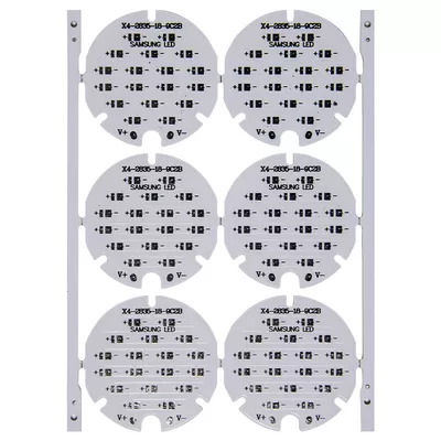
Name: 2OZ oz aluminum base circuit board
Number of layers: single-sided aluminum substrate
Plate thickness: 2.0MM
Copper thickness: 2OZ oz
Color: white text
Surface treatment: spray tin process
Breakdown voltage: 3000V
Thermal conductivity – thermal conductivity (W/m-k): 2.0
Application field: LED lighting
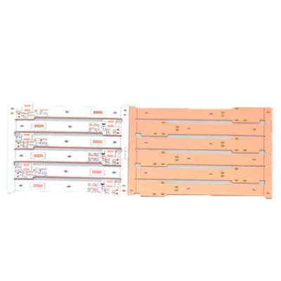
Thermoelectric separation copper-based circuit board
Name: Thermoelectric separation copper-based circuit board
Plate thickness: 2.0MM
Copper foil thickness: 3OZ
Thermal conductivity: 398w/m.k
Withstand voltage: AC1500V
Solder mask type: white oil
Surface treatment: OSP
E-T test: 100% computer open and short test
Production process: thermoelectric separation process
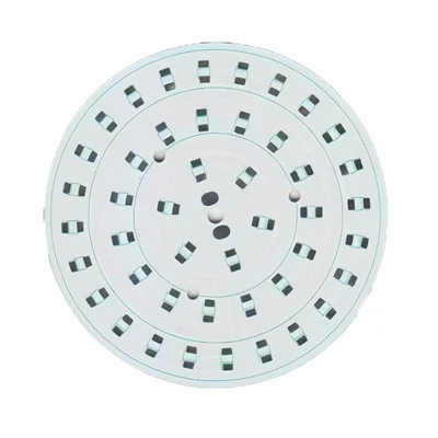
High thermal conductivity aluminum-based circuit board
Name: High thermal conductivity aluminum base circuit board
Number of layers: single-layer aluminum substrate
Plate thickness: 1.5MM
Copper thickness: 1OZ
Surface treatment: tin spray
Color: white oil black
Thermal conductivity: 3.0 (W/mk)
Withstand voltage KV: 1.5-3.5KV/AC
Application field: mining machine lighting
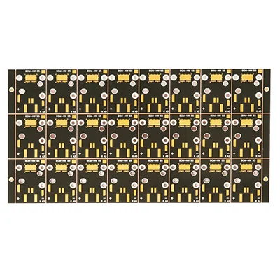
High thermal conductivity copper substrate
Name: High thermal conductivity copper substrate
Plate thickness: 1.0MM
Copper foil thickness: 2OZ
Withstand voltage: AC2000V
Thermal conductivity: 398w/m.k
Solder mask type: black oil
Surface Treatment: Immersion Gold
E-T test: 100% computer open and short test
Production process: thermoelectric separation process
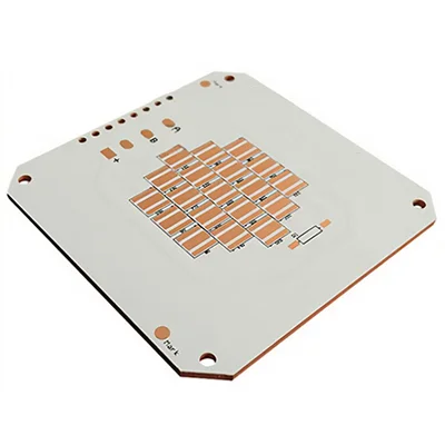
Product name: Copper base circuit board
Plate thickness: 1.6MM
Copper foil thickness: 2OZ
Withstand voltage: AC2000V
Thermal conductivity: 398w/m.k
Solder mask type: white oil
Surface treatment: OSP
E-T test: 100% computer open and short test
Production process: thermoelectric separation process
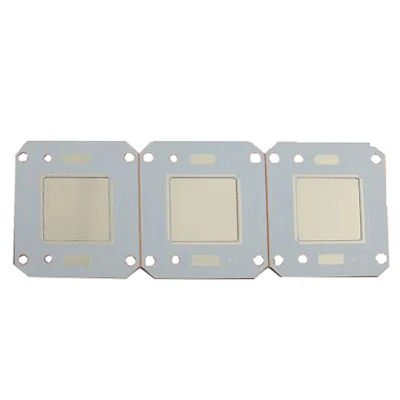
Double Sided Metal Core Copper Base MC PCB
Name: Double Sided Metal Core Copper Base MC PCB
PCB material: metal core copper base
Layers: 2
Copper weight: 6OZ
Solder mask: blue
Outline: Wiring, Punching, V-Cut
Solder mask: white/black/blue/green/red oil
Legend/Silkscreen Color: Black/White
Surface treatment: immersion gold, spray tin, OSP
Packing: vacuum/polybag
- Metal Core PCB Capability
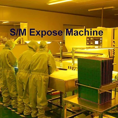
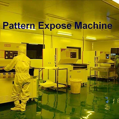
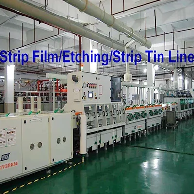
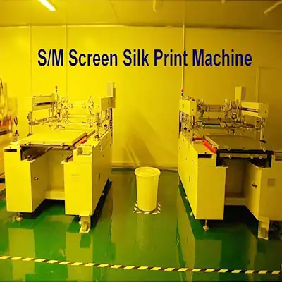
- PCB manufacturing equipment
Introducing our metal core PCB (MCPCBs), a specialized type of printed circuit board designed to provide excellent thermal management for high-power electronic applications. Our MCPCBs feature a metal core, typically aluminum or copper, which offers superior heat dissipation properties compared to traditional FR4 PCBs.
Our metal core PCBs are ideal for applications that require efficient heat transfer, such as LED lighting, power electronics, automotive lighting, and high-power electronic devices.
With their enhanced thermal conductivity and reliability, our MCPCBs ensure optimal performance and longevity of electronic systems operating under high-temperature conditions.
Metal Core PCBs (Printed Circuit Boards) are specialized circuit boards that have a metal core, typically aluminum or copper, as the base material instead of the traditional FR4 (Flame Retardant 4) material. The metal core provides improved heat dissipation and thermal management, making them suitable for applications that require efficient heat transfer.
The capability of Metal Core PCBs depends on several factors, including the manufacturing processes and materials used. Here are some key considerations:
- Metal Core Selection: The choice of metal core material affects the performance of the PCB. Aluminum and copper are commonly used due to their excellent thermal conductivity. Copper offers better conductivity but is costlier than aluminum.
- Layer Count: Metal Core PCBs can have multiple layers similar to standard FR4 PCBs. The layer count determines the complexity and functionality of the PCB.
- Heat Dissipation: Metal Core PCBs excel in dissipating heat generated by power components. The metal core acts as a heat sink, transferring heat away from heat-generating components to the surrounding environment.
- Copper Weight: The thickness of the copper layer affects the current-carrying capacity of the PCB traces. Typically, Metal Core PCBs have thicker copper layers to enhance their thermal and electrical performance.
- Dielectric Layer: The dielectric layer, also known as the insulating layer, separates the metal core from the copper traces. The choice of dielectric material affects the electrical properties and thermal conductivity of the PCB.
- Component Assembly: Metal Core PCBs support the same range of components as standard PCBs. Surface mount technology (SMT) and through-hole components can be used depending on the design requirements.
- Manufacturing Techniques: Metal Core PCBs are manufactured using similar processes as standard PCBs, including etching, plating, solder mask application, and component assembly. However, specialized techniques may be required to handle the unique characteristics of metal core materials.
- Design Considerations: Metal Core PCBs require careful consideration of thermal management and mechanical stability. Proper heat sinking, component placement, and thermal vias are essential to optimize the thermal performance.
Advantages of Metal Core PCB:
- Thermal Management: Metal core PCBs are specifically engineered to address thermal management challenges. The metal core acts as a highly conductive heat sink, efficiently dissipating heat generated by high-power components, such as LEDs or power transistors. This ensures reliable operation and prevents thermal damage to sensitive components.
- Enhanced Heat Dissipation: The metal core of our MCPCBs provides superior thermal conductivity compared to traditional PCB materials. Aluminum and copper, commonly used as metal cores, have excellent heat transfer properties. It allows for efficient dissipation of heat from the active components to the surrounding environment.
- Improved Power Handling: MCPCBs can handle higher power levels compared to standard FR4 PCBs. The metal core effectively spreads and dissipates heat, enabling electronic components to operate at their optimal power ratings without overheating. This results in increased power handling capacity and improved performance of high-power applications.
- Design Flexibility: Metal core PCBs offer design flexibility, allowing for the integration of different components and technologies. They support surface-mounted devices (SMDs), through-hole components, and can accommodate complex circuit layouts and high-density designs. This enables the realization of compact and efficient electronic systems.
- Electrical Isolation: Metal core PCBs provide electrical isolation between the metal core and the circuit traces. The metal core is electrically insulated using an appropriate dielectric layer. It ensures safe operation and preventing short circuits or electrical interference.
| Item | Capability |
| Layer Count | 1-40layers |
| Base Material | KB、Shengyi、ShengyiSF305、FR408、FR408HR、IS410、FR406、GETEK、370HR、IT180A、Rogers4350B、Rogers4000、PTFE Laminates(Rogers series、Taconic series、Arlon series、Nelco series)、Rogers/Taconic/Arlon/Nelco laminate with FR-4 material(including partial Ro4350B hybrid laminating with FR-4) |
| Board Type | Backplane、HDI、High multi-layer 、blind&buried PCB、Embedded Capacitance、Embedded resistance board 、Heavy copper power PCB、Backdrill. |
| Board Thickness | 0.2-5.0mm |
| Copper Thickness | Min. 1/2 OZ, Max. 10 OZ |
| PTH Wall | 25um(1mil) |
| Maximum Board Size | 1100*500mm(43”*19”) |
| Min laser drilling size | 4mil |
| Min. Spacing/Tracing | 2.7mil/2.7mil |
| Solder Mask | Green, Black, Blue, Red, White, Yellow, Purple matte/glossy |
| Surface Treatment | Flash gold(electroplated gold)、ENIG、Hard gold、Flash gold、HASL Lead-free 、OSP、ENEPIG、Soft gold、Immersion silver、Immersion Tin、ENIG+OSP, ENIG+Gold finger, Flash gold(electroplated gold)+Gold finger, Immersion silver+Gold finger, Immersion Tin+Gold finger. |
| Min. Annular Ring | 3mil |
| Aspect ratio | 10:1(HASL Lead-free 、HASL Lead、ENIG、Immersion Tin、Immersion silver、ENEPIG);8:1(OSP) |
| Impedance control | ±5ohm(<50ohm), ±10%(≥50ohm) |
| Other Techniques | Blind/Buried Via |
| Gold Fingers | |
| Press Fit | |
| Via in Pad | |
| Electrical Test |
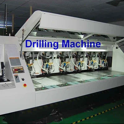
PCB Drilling machine
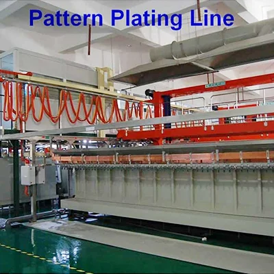
PCB pattern plating line
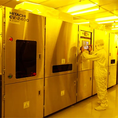
PCB solder mask expose machine
PCB pattern expose machine
Strip film etching line
Solder mask screen silk print machine
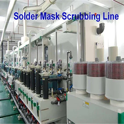
Solder mask scrubbing line
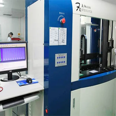
PCB Flying Probe Test (FPT)
Fully automatic exposure machine

