DC Controller PCB Assembly: A Comprehensive Guide
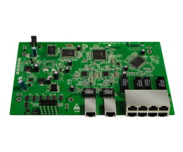
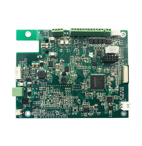
DC controller PCB assembly is a critical process in the manufacturing of electronic devices that require DC power. The DC controller PCB is a printed circuit board that regulates and controls the flow of DC power in electronic devices. It is an essential component in many electronic devices, including printers, scanners, and power supplies.

DC controller PCB assembly involves the use of various components, including resistors, capacitors, diodes, and transistors. These components are soldered onto the PCB to create a circuit that regulates the flow of DC power. The assembly process requires a high level of precision and attention to detail to ensure that the PCB functions correctly and reliably.
If you are involved in the manufacturing of electronic devices, it is essential to have a good understanding of DC controller PCB assembly. It is a complex process that requires specialized skills and knowledge. By mastering this process, you can ensure that your electronic devices are reliable and function correctly.
Overview of DC Controller PCB Assembly

DC controller PCB assembly is the process of manufacturing a printed circuit board that regulates and controls the flow of DC power in electronic devices. The DC controller PCB is a crucial component of any electronic device that runs on DC power, such as a computer, a printer, or a power supply.
The DC controller PCB assembly process involves several steps, including designing the circuit board, selecting the components, and assembling the board. The design of the circuit board is critical because it determines how the board will function and how it will interact with other components in the device. The components selected for the assembly must be of high quality and compatible with the board’s design.
During the assembly process, the components are mounted onto the circuit board, and the board is tested to ensure that it functions correctly. Any errors or defects in the assembly process can cause the board to malfunction or fail, leading to problems with the device.
To ensure the quality of the DC controller PCB assembly, it is essential to use high-quality components and follow strict manufacturing processes. Quality control measures, such as testing and inspection, are also critical to ensuring that the board functions correctly and meets the device’s specifications.
Overall, the DC controller PCB assembly is a complex and critical process in the manufacturing of electronic devices. It requires expertise, precision, and attention to detail to ensure that the board functions correctly and meets the device’s specifications.
Components of DC Controller PCBs

DC controller PCBs are critical components in the manufacturing of electronic devices that require DC power. These PCBs regulate and control the flow of DC power in electronic devices. DC controller PCBs consist of several components, including microcontrollers and processors, power management ICs, and connectivity modules.
Microcontrollers and Processors
Microcontrollers and processors are essential components of DC controller PCBs. These components are responsible for controlling and regulating the flow of DC power in electronic devices. They are programmable, which means that they can be customized to perform specific functions. Microcontrollers and processors are available in various types and sizes, depending on the specific requirements of the electronic device.
Power Management ICs
Power management ICs are another critical component of DC controller PCBs. These components are responsible for managing the power supply to the electronic device. They regulate the voltage and current levels to ensure that the electronic device operates within safe limits. Power management ICs are available in various types, including linear regulators, switching regulators, and voltage references.
Connectivity Modules
Connectivity modules are also essential components of DC controller PCBs. These modules enable the electronic device to communicate with other devices or networks. They provide wireless connectivity, such as Wi-Fi, Bluetooth, and cellular connectivity. Connectivity modules are available in various types and sizes, depending on the specific requirements of the electronic device.
In summary, DC controller PCBs consist of several components that regulate and control the flow of DC power in electronic devices. These components include microcontrollers and processors, power management ICs, and connectivity modules. Each component plays a critical role in ensuring that the electronic device operates within safe limits and performs its intended function.
Assembly Process for DC Controller PCBs
DC controller PCB assembly is a critical process in the manufacturing of electronic devices that require DC power. The DC controller PCB is a printed circuit board that regulates and controls the flow of DC power in electronic devices. Here is a brief overview of the assembly process for DC controller PCBs.
Surface-Mount Technology
Surface-mount technology (SMT) is a method for mounting electronic components on the surface of a printed circuit board (PCB). SMT components are smaller and lighter than through-hole components, making them ideal for high-density PCB designs. The SMT process involves the following steps:
- Stenciling: A stencil is used to apply solder paste to the PCB.
- Pick-and-Place: An automated machine picks up SMT components from a reel or tray and places them on the PCB.
- Reflow Soldering: The PCB is heated in a reflow oven, causing the solder paste to melt and form a permanent bond between the components and the PCB.
Through-Hole Technology
Through-hole technology (THT) is a method for mounting electronic components on a printed circuit board by inserting the leads of the components through holes in the PCB and soldering them to pads on the opposite side. THT components are larger and heavier than SMT components, making them more suitable for applications where size and weight are not critical. The THT process involves the following steps:
- Drilling: Holes are drilled in the PCB where the through-hole components will be inserted.
- Component Insertion: The leads of the through-hole components are inserted through the holes in the PCB.
- Wave Soldering: The PCB is passed over a wave of molten solder, which flows through the holes and forms a permanent bond between the components and the PCB.
The assembly process for DC controller PCBs involves both surface-mount and through-hole technologies. The choice of technology depends on the specific requirements of the application.
Testing and Quality Assurance in PCB Assembly
When it comes to PCB assembly, testing and quality assurance are crucial steps that ensure the final product meets the required standards. In this section, we will discuss two important methods of testing and quality assurance in PCB assembly: Automated Optical Inspection and Functional Testing.
Automated Optical Inspection
Automated Optical Inspection (AOI) is a non-contact test method that uses a camera to inspect the surface of the PCB assembly. AOI is a fast and reliable method that can detect a wide range of defects, including missing components, incorrect component placement, and soldering defects. AOI can also detect defects that are not visible to the naked eye, such as hairline cracks, cold solder joints, and insufficient solder paste.
AOI machines use algorithms to compare the images of the PCB assembly with the design data to detect defects. AOI machines can also create reports that show the locations and types of defects, which can help improve the manufacturing process.
Functional Testing
Functional Testing is a method of testing the PCB assembly by applying power and signals to the board and checking its response. Functional testing can detect defects that are not detected by AOI, such as incorrect component values, incorrect polarity, and incorrect programming.
Functional testing can be performed manually or automatically. Manual testing involves connecting the board to a test fixture and manually applying power and signals to the board. Automatic testing involves using a test program that automatically applies power and signals to the board and checks its response.
Testing and quality assurance are critical steps in PCB assembly that ensure the final product meets the required standards. AOI and functional testing are two important methods that can detect a wide range of defects and improve the manufacturing process.
Applications of DC Controller PCBs
DC controller PCBs are widely used in various electronic devices, from industrial automation to consumer electronics. Here are some common applications of DC controller PCBs:
Industrial Automation
DC controller PCBs are extensively used in industrial automation systems, such as robotics, conveyor belts, and automated assembly lines. These systems require precise control of DC power to ensure smooth operation and avoid damage to machinery. DC controller PCBs allow for accurate regulation of voltage and current, ensuring that the machinery receives the right amount of power at all times.
Consumer Electronics
DC controller PCBs are also used in various consumer electronics, such as laptops, smartphones, and gaming consoles. These devices require efficient and reliable power management to ensure optimal performance and battery life. DC controller PCBs enable efficient power conversion and supply across various voltage levels, minimizing power loss and maximizing battery life.
In addition, DC controller PCBs can also be found in:
- Electric vehicles: DC controller PCBs regulate the flow of power between the battery and the motor, ensuring efficient operation and maximum range.
- Renewable energy systems: DC controller PCBs are used in solar panels, wind turbines, and other renewable energy systems to convert DC power into AC power for use in homes and businesses.
- Medical devices: DC controller PCBs are used in various medical devices, such as ultrasound machines and MRI scanners, to regulate the flow of power and ensure accurate readings.
Overall, DC controller PCBs play a crucial role in modern electronic devices, enabling efficient power management and reliable operation.
Challenges and Solutions in DC Controller PCB Assembly
DC controller PCB assembly is a complex process that requires careful attention to detail. There are various challenges that can arise during this process, but with the right solutions, these challenges can be overcome.
Thermal Management
One of the biggest challenges in DC controller PCB assembly is thermal management. As electronic devices continue to become more powerful, they generate more heat, which can cause damage to the PCB and other components.
To address this issue, it is important to design the PCB with thermal management in mind. This can include using heat sinks, thermal vias, and other techniques to dissipate heat away from critical components. Additionally, it is important to use high-quality materials that can withstand high temperatures.
Signal Integrity Issues
Another common challenge in DC controller PCB assembly is signal integrity issues. These issues can arise when signals are corrupted or lost due to interference or other factors.
To ensure signal integrity, it is important to use proper routing techniques and design the PCB with signal integrity in mind. This can include using ground planes, minimizing the length of signal traces, and using differential signaling where appropriate.
By addressing these challenges and implementing the right solutions, you can ensure that your DC controller PCB assembly is successful and reliable.


