Electronics PCB Components Assembly: A Comprehensive Guide
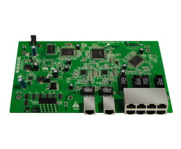
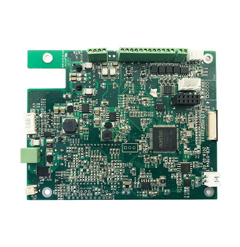
If you’re interested in electronics, you’ve probably heard the term PCB before. PCB stands for printed circuit board, and it’s a vital component in many electronic devices. A PCB is essentially a board with lines and pads that connect various points together. These lines and pads are made of copper, and the board itself is made of insulating material.

But what about the components that go on the PCB? The components are what make the PCB useful. They include things like resistors, capacitors, and transistors, and they’re what allow the PCB to do its job. The process of attaching these components to the PCB is called assembly, and it’s a critical step in creating a functional electronic device. There are several different methods for assembling PCB components, including surface mount technology (SMT) and through-hole technology (THT). Each method has its own advantages and disadvantages, and the choice of method will depend on factors like the complexity of the device and the intended use.
Basics of PCB Components

When it comes to electronics assembly, printed circuit boards (PCBs) are a critical component. PCBs provide a platform for the assembly and connection of various electronic components, making them an essential part of modern electronic devices. In this section, we will cover the basics of PCB components, including active vs passive components and surface mount vs through-hole technology.
Active vs Passive Components
PCB components can be divided into two main categories: active and passive components. Active components are those that require a power source to operate, such as transistors and integrated circuits. Passive components, on the other hand, do not require a power source and include components such as resistors, capacitors, and inductors.
Active components are often used to amplify signals, while passive components are used to filter, store, and regulate signals. When designing a PCB, it is essential to consider the types of components needed and how they will interact with one another.
Surface Mount vs Through-Hole Technology
Another important consideration when designing a PCB is the type of technology used to mount components on the board. Two common technologies are surface mount technology (SMT) and through-hole technology.
SMT involves mounting components directly onto the surface of the PCB, which can save space and reduce the overall size of the board. Through-hole technology, on the other hand, involves drilling holes in the PCB and mounting components through the holes.
While SMT is becoming more popular due to its smaller size and lower cost, through-hole technology is still widely used for components that require higher power or have larger leads. When choosing a technology, it is important to consider the specific needs of the project and the requirements of the components being used.
In summary, understanding the basics of PCB components is essential for designing and assembling electronic devices. By considering factors such as active vs passive components and surface mount vs through-hole technology, you can create a PCB that meets the specific needs of your project.
PCB Assembly Process

When it comes to printed circuit board (PCB) assembly, there are several techniques that can be used to populate the board with components. Depending on the complexity of the board and the number of components that need to be assembled, the process can be done manually or by automated machines. In this section, we will discuss the three main techniques used in PCB assembly: soldering, automated assembly, and manual assembly.
Soldering Techniques
Soldering is the process of joining two metal surfaces together using a filler metal (solder). There are two main types of soldering techniques used in PCB assembly: through-hole and surface mount. Through-hole soldering involves inserting components with leads into holes on the PCB and then soldering the leads to the board. Surface mount soldering involves attaching components directly to the surface of the PCB using solder paste and a reflow oven.
Automated Assembly
Automated assembly is a process in which machines are used to place and solder components onto the PCB. This process is typically used for high-volume production runs where speed and consistency are important. The machines used in automated assembly are capable of placing components with high precision and speed, and can also inspect the components to ensure they are properly placed and soldered.
Manual Assembly
Manual assembly is a process in which components are placed and soldered onto the PCB by hand. This process is typically used for low-volume production runs or for prototypes. Manual assembly requires skilled technicians who are capable of placing components with precision and soldering them properly. While manual assembly is slower and less consistent than automated assembly, it can be more cost-effective for small production runs.
The PCB assembly process can be done using various techniques, each with their own advantages and disadvantages. Whether you choose to use soldering techniques, automated assembly, or manual assembly, it’s important to ensure that the components are properly placed and soldered to ensure the functionality and reliability of the final product.
Design Considerations

When designing a PCB for component assembly, there are several important considerations to keep in mind. Here are some key factors to consider:
PCB Layout
The PCB layout is an important factor to consider when designing a PCB for assembly. The layout should be optimized for ease of assembly, which means that components should be placed in a logical and efficient manner. This can help to reduce the time and cost of assembly, as well as improve the overall quality of the finished product.
Component Placement
Component placement is another important consideration when designing a PCB for assembly. Components should be placed in a way that allows for easy access during assembly, as well as optimal thermal management. This can help to prevent overheating and other issues that can impact the performance of the finished product.
Thermal Management
Thermal management is a critical consideration when designing a PCB for assembly. Overheating can cause components to fail, which can impact the performance and reliability of the finished product. To prevent this, it is important to design the PCB with proper thermal management in mind. This can include the use of heat sinks, thermal vias, and other techniques to help dissipate heat and keep the temperature of the PCB within safe limits.
Overall, designing a PCB for component assembly requires careful consideration of a variety of factors. By optimizing the PCB layout, component placement, and thermal management, you can help to ensure that the finished product is of high quality and reliable.
Testing and Quality Assurance

When it comes to electronics PCB components assembly, testing and quality assurance are critical to ensure the functionality, reliability, and quality of the printed circuit boards. In this section, we will discuss two main subsections of testing and quality assurance, Inspection Methods, and Functional Testing.
Inspection Methods
Inspection methods are used to assess the bare PCB quality and yield and to ensure that the design has passed through assembly without defects. There are two main types of inspection methods, visual inspection, and electrical inspection.
Visual Inspection
Visual inspection is a manual inspection method that uses a magnifier or the technician’s bare eyes to find solder defects and other visible defects such as component orientation. This method is generally used for identifying defects like solder bridges, missing components, and incorrect component orientation.
Electrical Inspection
Electrical inspection is performed during manufacturing/assembly and compared with the design netlist. Electrical inspection involves testing the functionality of the circuitry, including the power supply, ground connections, and signal routing. This method is generally used to identify defects like short circuits, open circuits, and incorrect values of resistors, capacitors, and other components.
Functional Testing
Functional testing is a comprehensive testing method that involves powering up and actuating individual circuitry on the PCB to check for defects. There are two main types of functional testing methods, In-Circuit Testing (ICT) and Flying Probe Testing.
In-Circuit Testing (ICT)
In-Circuit Testing (ICT) is a robust and comprehensive testing method that provides high coverage and can identify issues with solder connections, component failures, or faulty circuitry. ICT involves powering up and actuating individual circuitry on the PCB to check for defects.
Flying Probe Testing
Flying Probe Testing is a non-invasive testing method that involves using a specialized testing machine to probe the PCB and check for defects. This method is generally used for low-volume production runs and prototypes, where the cost of creating an in-circuit test fixture is not justified.
Testing and quality assurance are critical to ensure the functionality, reliability, and quality of the printed circuit boards. Inspection methods and functional testing are two main subsections of testing and quality assurance that help identify defects and optimize performance.
Future Trends in PCB Assembly

As technology continues to evolve, the future of PCB assembly is set to witness significant advancements. Here are some of the emerging trends that are likely to shape the future of PCB assembly:
Advancements in SMT
Surface Mount Technology (SMT) is a technique that is used to mount electronic components onto the surface of a PCB. SMT has been around for a while, but advancements in this technology are set to revolutionize PCB assembly. One of the main advantages of SMT is that it allows for smaller and more compact PCBs. This is because SMT components are smaller and can be placed closer together on the board. In addition, SMT components have better thermal conductivity, which means they dissipate heat more efficiently.
Emerging Technologies
The electronics industry is constantly evolving, and new technologies are emerging all the time. One of the emerging technologies that is likely to have a significant impact on PCB assembly is 3D printing. 3D printing has the potential to revolutionize the way PCBs are designed and manufactured. With 3D printing, it is possible to create complex PCB designs that would be difficult or impossible to produce using traditional manufacturing methods.
Another emerging technology that is likely to have an impact on PCB assembly is Artificial Intelligence (AI). AI has the potential to optimize the manufacturing process by identifying inefficiencies and suggesting improvements. For example, AI could be used to optimize the placement of components on a PCB to reduce the risk of interference and improve the performance of the device.
In conclusion, the future of PCB assembly is set to witness significant advancements with the emergence of new technologies and advancements in existing ones. As electronic devices continue to become more compact and powerful, PCB assembly will play a critical role in enabling these devices to function effectively.


